Your Trusted Electrical Knowledge Partner
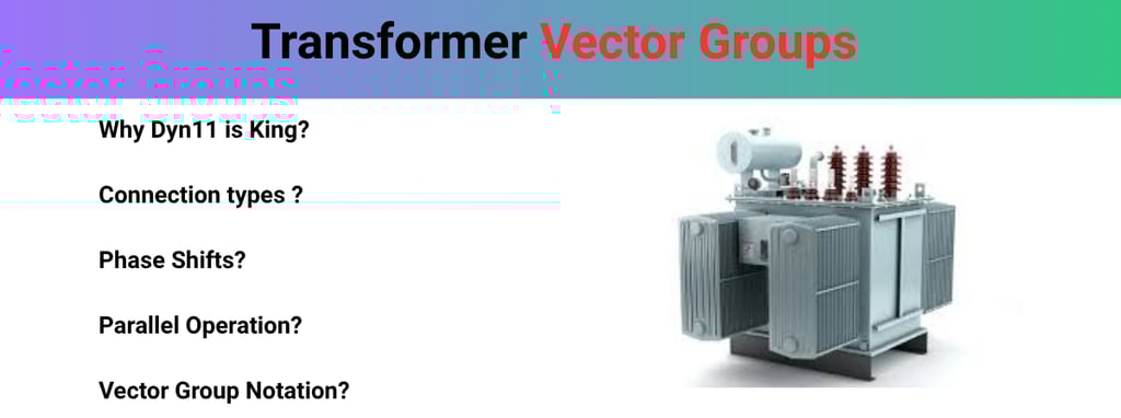
Transformer Vector Groups: A Practical Guide for Electrical Professionals
Transformer Vector Groups: This practical guide explains transformer vector groups and their role in phase displacement, parallel operation, and system protection, using clear symbols, examples, and real‑world applications for electrical professionals.
Transformer Vector Groups: A Practical Guide for Electrical Professionals
In the world of high-voltage engineering, connecting a transformer isn’t just about matching the voltage levels. If you have ever stood in a substation or a plant floor, you know that the "invisible" relationship between the primary and secondary waves is what truly dictates whether a system runs smoothly or ends in a catastrophic flashover. This relationship is defined by the Transformer Vector Group.
Whether you are a field engineer commissioning a new unit or a technician troubleshooting a tripped breaker, understanding vector groups is non-negotiable. In this guide, we will break down the complexities of phase displacement, clock notation, and the practical implications of selecting the right group for your system.
What is a Transformer Vector Group?
At its core, a Transformer Vector Group is a shorthand code that describes two things:
Winding Configuration: How the internal coils are connected (Star, Delta, or Zig-Zag).
Phase Displacement: The angular difference between the High Voltage (HV) and Low Voltage (LV) terminals.
In a three-phase system, the AC sine waves of the secondary side don't always line up perfectly with the primary side. Depending on how we wrap and connect the coils, the secondary voltage can "lead" or "lag" the primary voltage. We represent this using an alphanumeric code like Dyn11 or Yd1.
Hindi Translation: Transformer vector group winding configuration aur primary aur secondary windings ke beech phase displacement ka symbolic representation hota hai. Ye generally alphanumeric form me likha jata hai jaise Dyn11, Yd1, Yy0, etc. Ye symbols polarity, phase shift aur connection type ke bare me important information dete hain.
Why Vector Groups Matter in the Real World
You might wonder, "If the voltage ratio is correct, why does the vector group matter?" The answer lies in Parallel Operation.
Imagine trying to gear two spinning wheels together. If their teeth don't align perfectly, the gears will clash and break. Similarly, if you connect two transformers in parallel with different vector groups, you are essentially creating a short circuit between the phases.
Circulating Currents: Even a small phase mismatch causes massive currents to flow between the transformers, leading to overheating.
System Stability: Incorrect vector groups can cause protection relays to trip unnecessarily.
Harmonic Management: Certain connections (like Delta) are essential for "trapping" the 3rd harmonic, preventing it from polluting the grid.
The Three Pillars: Winding Connections
Before we decode the symbols, we must understand the three ways windings are physically connected inside the tank:
1. Star (Y) Connection- The ends of the three windings are joined at a common "neutral" point.
Practical Use: Ideal for providing a neutral wire for single-phase loads.
Math Tip: In Star, I (line) = I (phase).
Key takeaway:-
Line voltage is √3 times the phase voltage
Line current is equal to phase current
2. Delta (D) Connection- The windings are connected end-to-end in a closed loop (triangle).
Practical Use: Excellent for industrial loads and suppressing harmonics. It does not naturally provide a neutral.
Math Tip: In Delta, V (line) = V (phase).
Key takeaway (Delta Δ Connection):-
Line voltage is equal to phase voltage
Line current is √3 times higher than phase current
3. Zig-Zag (Z) Connection- A special "interconnected star" connection where each phase is split between two different limbs of the core.
Practical Use: Primarily used for earthing transformers to provide a neutral point on an ungrounded Delta system.
Decoding the Notation: The "Clock" Method
To make it easy for engineers worldwide, we use a Clock Notation. Imagine the High Voltage (HV) winding vector is the "Minute Hand" of a clock, fixed forever at 12. The Low Voltage (LV) winding vector is the "Hour Hand."
Each hour on the clock represents a 30° shift.
0 or 12: No phase shift ($0°$).
1: 30° Lag (The LV lags the HV).
6: 180° Phase shift (Inverted).
11: 330° Lag (or 30° Lead).
Notation Structure:
Capital Letter: HV Winding (D=Delta, Y=Star).
Small Letter: LV Winding (d=delta, y=star, z=zig-zag).
'n': If present, it means the neutral is brought out to a terminal.
The Number: The clock position.
Practical Deep-Dive:
The Dyn11 Vector Group- In distribution networks (like the transformer on your street), Dyn11 is the king. Let’s break it down:
D: High Voltage side is connected in Delta (usually 11kV or 33kV).
y: Low Voltage side is connected in Star.
n: The neutral point of the Star is brought out (allowing us to have 230V for homes).
11: The LV phase leads the HV phase by 30° (or lags by 330°).
Why Dyn11?
In a distribution system, loads are often unbalanced (one house uses more power than the next). The Delta primary allows the unbalanced currents to circulate without disturbing the upstream transmission line, while the Star secondary provides the essential neutral wire for 1-phase appliances.
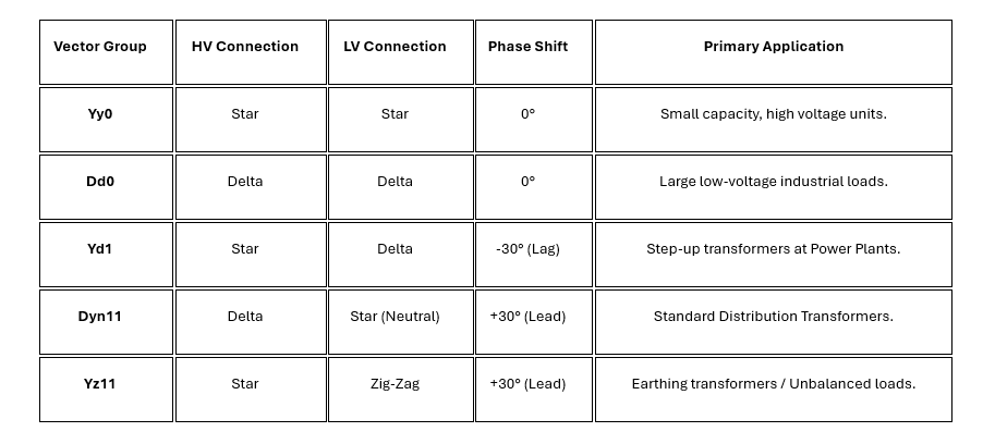
Comparative Table: Common Vector Groups

Critical Requirements for Parallel Operation :
If you are tasked with adding a second transformer to an existing busbar to increase capacity, you must check these four "Golden Rules." If the vector groups don't match, you cannot proceed.
Same Voltage Ratio: To avoid circulating currents.
Same Frequency: (50Hz or 60Hz depending on your country).
Same Percentage Impedance (%Z): To ensure they share the load proportionally.
SAME VECTOR GROUP: This is the "Phase Sequence" check.
Pro-Tip from the Field: You can sometimes parallel a Group 3 (e.g., Dyn1) with a Group 4 (e.g., Dyn11) by swapping external cables, but you can never parallel a Group 1 (0° shift) with a Group 3 (30° shift).
How to Test Vector Groups on Site -
When a new transformer arrives, you shouldn't just trust the nameplate. We perform a Vector Group Verification Test:
Shorting Leads: Connect one HV phase terminal to one LV phase terminal (usually A2 to a2).
Applying Voltage: Apply a low-voltage 3-phase supply (e.g., 415V) to the HV side.
Measurement: Measure the voltages between all other terminals (A-b, A-c, B-b, etc.).
Verification: Compare the measured voltages against the mathematical expectations of the specific vector group. For a Dyn11 transformer, the voltage $V_{Bb}$ must equal $V_{Bc}$.